Modulation and Synchronization
Block 8. Modulation and Synchronization
Purpose
This block introduces digital modulation, demodulation, and core synchronization mechanisms in time, frequency, and phase.
Why this block matters
It turns SDR from a tone-observation tool into an information-transmission system and links DSP to an actual receiver.
Main topics
- BPSK, QPSK, and basic constellations;
- pulse shaping;
- symbol timing recovery;
- carrier and phase synchronization;
- decision devices and BER;
- debugging a modulator and a demodulator.
Practical work
- building a modulator-channel-demodulator chain;
- observing constellations and eye diagrams;
- experiments with frequency and timing mismatch;
- estimating synchronization errors and reception quality.
Tooling for the block
The main toolset is: MATLAB, Simulink, GNU Radio, Python.
Expected outputs
- constellations before and after synchronization;
- BER or decision-error plots;
- synchronization-chain description;
- modulation/demodulation report.
Folder structure
block_08_modulation_and_synchronization/
├── README.md
├── README_ru.md
├── README_en.md
├── CONTENTS_ru.md
├── CONTENTS_en.md
├── assets/
├── images/
├── kicad/
├── simulink/
├── matlab/
├── python/
├── cpp/
├── gnuradio/
└── reports/
assets/— reference data and helper materials;images/— diagrams, screenshots, and photos;kicad/— schematics and electrical notes;simulink/,matlab/,python/,cpp/,gnuradio/— models and analysis tools;reports/— reports and report templates.
Recommended work order
- assemble a basic digital link.
- visualize constellations and time diagrams.
- inject synchronization errors and compensate them.
- formulate limits and conclusions.
Learning routes
| Route | Labs | Engineering result |
|---|---|---|
| QPSK modem | 8.8 — impairments and BER → 8.9 — carrier recovery | Gray mapping, BER and CFO/phase recovery |
| OFDM | 8.5 — mini link → 8.10 — PAPR and clipping | End-to-end link plus implementation back-off and spectral-regrowth trade-offs |
| Waveform comparison | 8.11 — 16-QAM → 8.12 — GFSK → 8.13 — DSSS | Spectral efficiency, envelope, synchronization and FPGA-cost trade-offs |
| CSS | 8.20 — waveform → 8.21 — dechirp/FFT → 8.22 — packet sync/PER | Chirp mapping, FFT-bin detection, packet acquisition and PER |
The numbering groups related extensions intentionally: 8.8–8.9 continue QPSK, 8.10 extends OFDM, and 8.20–8.22 form the CSS track.
The CSS track now includes a compact, bit-exact SF7 RTL accelerator baseline. It is intentionally separate from the complete LoRa PHY in the companion project. The AXI integration guide defines its stream packets, AXI-Lite registers, IRQ, and remaining board-level work.
Real hardware BPSK — spectrum, constellation & SNR/EVM
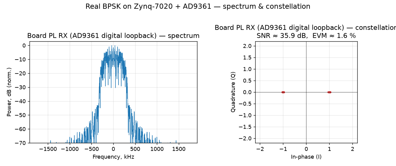
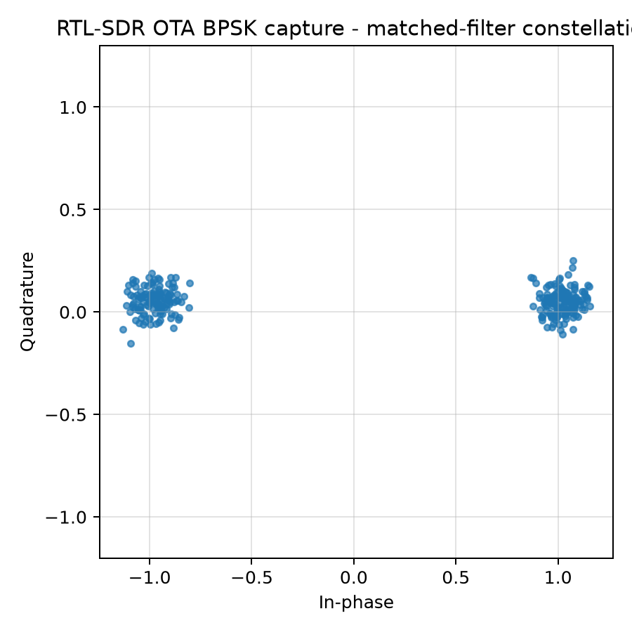
Real measured BPSK from the course board (Zynq-7020 + AD9361): the same three quantities you compute in theory — power spectrum, constellation, and SNR / EVM — taken from the running hardware, comparing the on-chip FPGA receiver in AD9361 digital loopback with an independent RTL-SDR over the air.
| Metric | Board PL RX (digital loopback) | RTL-SDR (over the air, ~10 cm) |
|---|---|---|
| EVM | ≈ 1.6 % | ≈ 10.6 % |
| SNR (from EVM) | ≈ 36 dB | ≈ 19.5 dB |
| Carrier frequency offset | 0 (digital, no carrier) | ≈ +2.7 kHz |
| BER | 0 | 0 |
The internal loopback isolates the modem — two tight clusters at I = ±1, Q ≈ 0, no carrier. Over the air the radio channel spreads the clusters with noise and rotates them with the carrier frequency offset (Lab 8.1 / 8.2 seen on real hardware), yet at close range it still decodes at BER 0. The visual gap between the two constellations is the RF channel. Full walkthrough, numbers and reproduction: Lab 8.7 — Real-hardware BPSK metrics.
QPSK — two bits per symbol, impairments & BER
QPSK is two independent BPSK axes (Gray-coded: low bit → I, high bit → Q), so it doubles the bit rate at the same bandwidth. A synthesizable QPSK modem reusing the shared upsampler / RRC / sampler recovers a full frame at BER = 0 in HDL loopback; a channel simulation then shows what the two impairments of this block do to it:
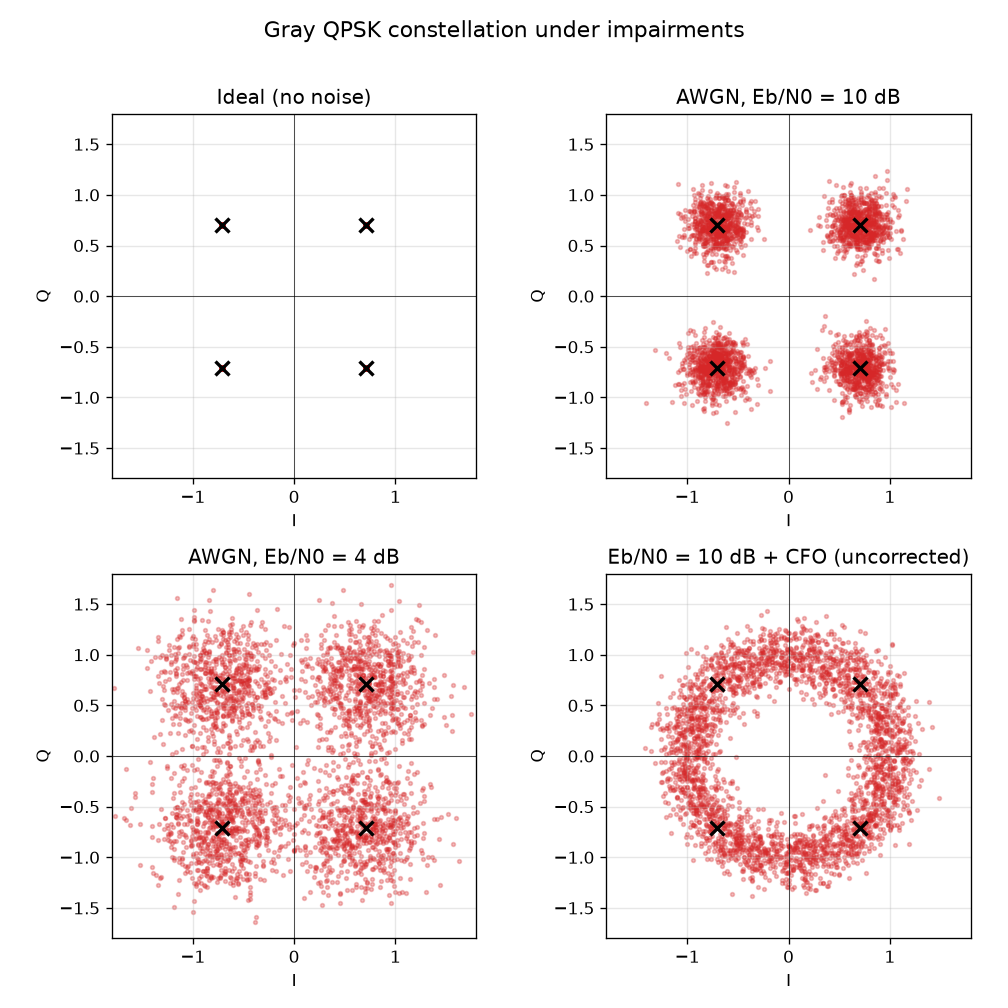
Four clean points → noise-spread clouds → (at low Eb/N0) clouds crossing the axes = bit errors; an uncorrected carrier frequency offset rotates the four points into a ring, undecodable until a carrier-recovery loop de-rotates it (Lab 8.1 / 8.2).
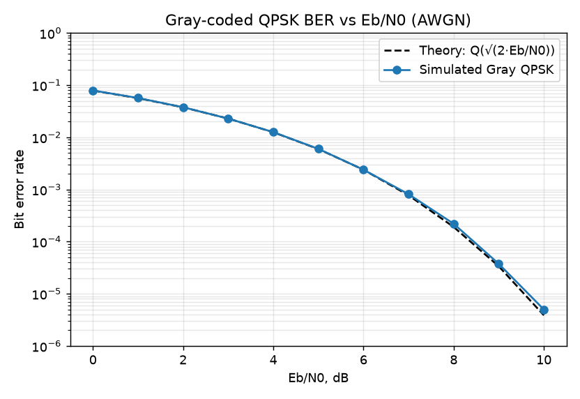
Being two orthogonal BPSK axes, Gray QPSK has the same per-bit BER as BPSK,
Q(√(2·Eb/N0)) — the simulation matches theory across 0–10 dB. Full walkthrough:
Lab 8.8 — QPSK modem, impairments and BER.
QPSK carrier recovery — de-rotating the CFO ring
The CFO ring above is undecodable (BER ≈ 0.5) until a carrier-recovery loop de-rotates it. A decision-directed Costas loop (NCO + PI loop filter + QPSK phase-error detector — the frequency-domain twin of the Gardner timing loop) drives the ring back onto the four points and tracks the CFO ramp:
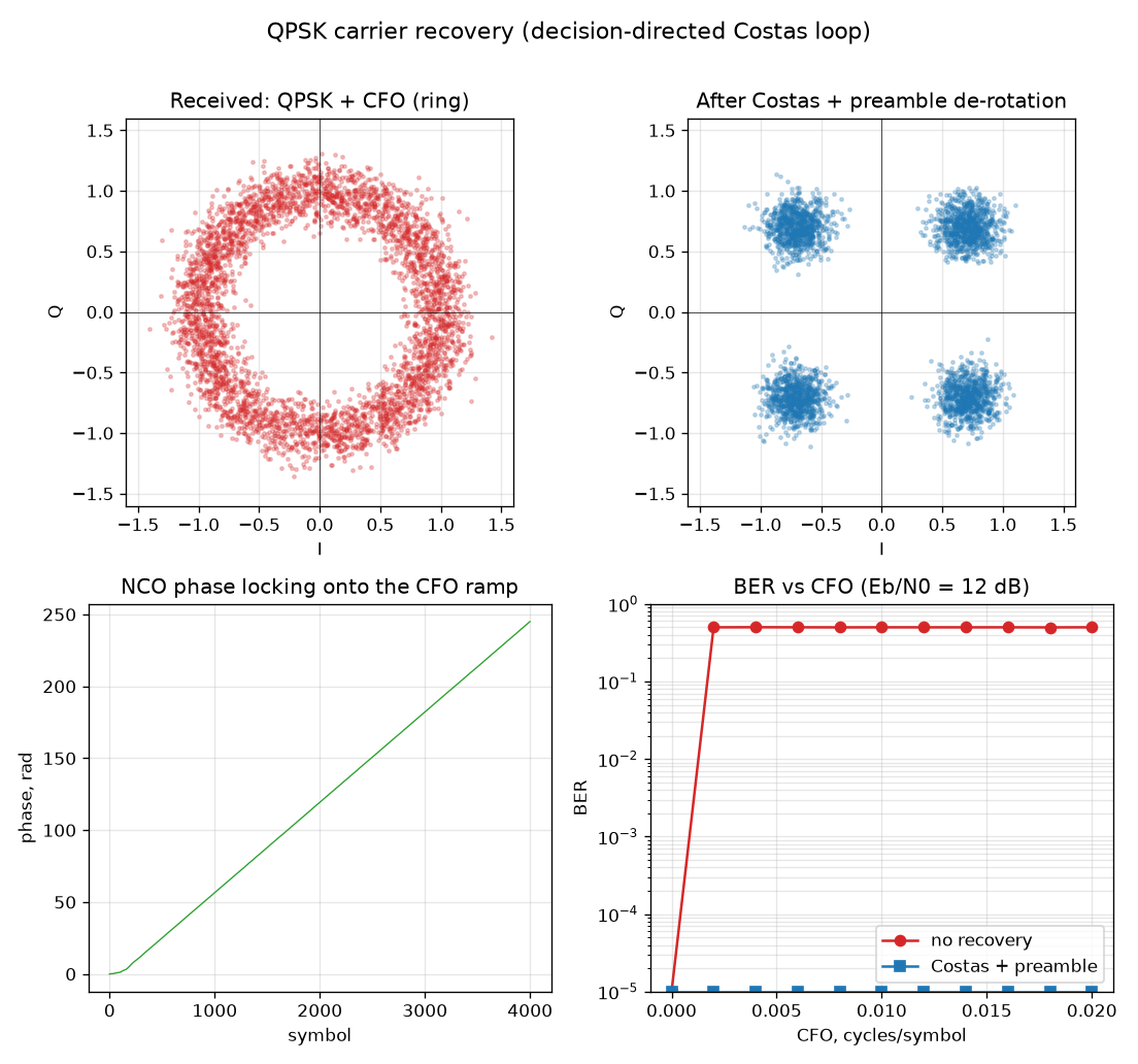
The one twist BPSK does not have: the loop locks to one of four k·90° rotations, so the
constellation looks perfect but the bit labelling may be rotated (the 90° ambiguity). The
same known preamble the modem uses for frame sync resolves it — turning the noisy BER back
into a flat BER = 0 across the whole CFO sweep. Full walkthrough:
Lab 8.9 — QPSK carrier recovery.
QPSK on real hardware — board loopback vs over the air
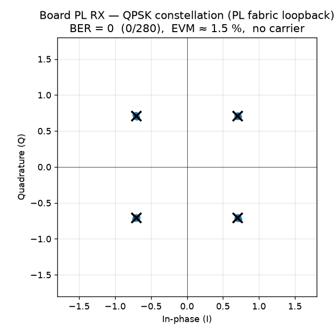
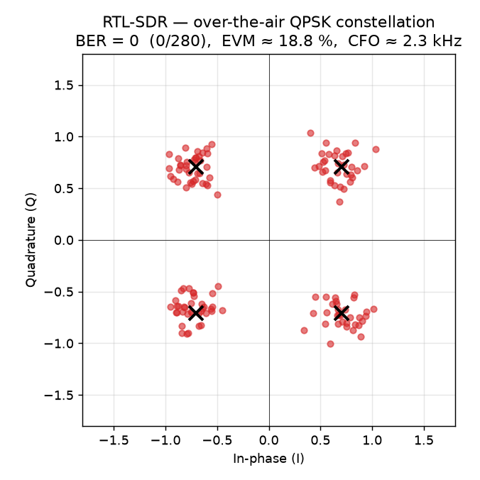
The same three quantities as the BPSK measurement above, now for QPSK: the board's own PL receiver in fabric loopback (the modem isolated — no RF, no carrier) versus an independent RTL-SDR over the air. The host demodulator does exactly what this block teaches: coarse + fine carrier-frequency-offset search, an RRC matched filter, preamble frame-sync, and a four-way 90° quadrant resolve.
| Metric | Board PL RX (fabric loopback) | RTL-SDR (over the air, ~1–2 cm) |
|---|---|---|
| EVM | ≈ 1.5 % | ≈ 19 % |
| SNR (from EVM) | ≈ 36 dB | ≈ 14.5 dB |
| Carrier frequency offset | 0 (digital, no carrier) | ≈ +2.3 kHz |
| BER | 0 (0/280) | 0 (0/280) |
Four razor-tight dots in loopback (the modem isolated) become four noise-spread, carrier-rotated clouds over the air (the radio channel), yet both decode at BER = 0 through the same synchronization chain the simulations model. The visual gap between the two constellations is the RF channel — exactly the BPSK story of Lab 8.7, now at two bits per symbol.
Next step
After finishing this block, the student should be ready to reuse its results as the starting point for the next stage of the course and the related practical experiment.