Lab 10.6 — Digital RF Attenuator: Step, Range and Linearity Check
Goal
Characterize a 0…31.75 dB digital RF attenuator with 0.25 dB steps as a controllable element of the SDR bench. The lab turns manual level setting into reproducible sweep experiments for SNR, BER, ADC overload, level margin and measurement repeatability.
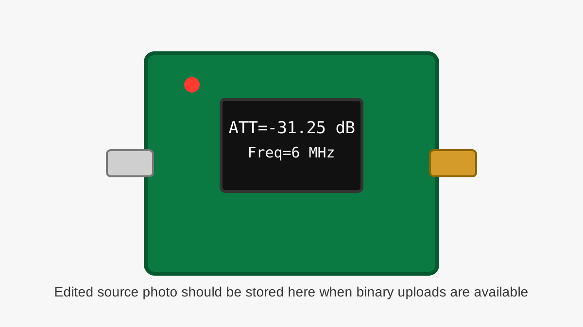
Equipment
- digital RF attenuator with SMA input/output and USB power;
- NanoVNA, signal generator/spectrum analyzer, or SDR TX/RX pair;
- 50-ohm cables and loads;
- fixed protective 10–30 dB attenuator for TX/RX loopback;
- measurement log or CSV file.
Safety
Do not use the digital attenuator as the only protection element during the first transmitter-to-receiver connection. Start with a fixed attenuator and verify the power budget. The digital attenuator is convenient for sweeps, but its maximum input power and matching must be validated separately.
What to measure
- Zero setting: actual insertion loss at
ATT = 0 dB. - Attenuation error at 0, 3, 6, 10, 20, 30 and 31.75 dB.
- Repeatability when returning to the same setting.
- Frequency dependence: at least two frequencies, for example 10 MHz and the SDR operating frequency.
- SDR behavior: how dBFS level, SNR and BER change during an attenuation sweep.
NanoVNA procedure
- Warm up the instruments for 5–10 minutes.
- Perform a
Thrucalibration for the cables without the attenuator. - Insert the attenuator between the NanoVNA ports.
- For each
ATT_set, saveS21at the selected frequency. - Compute the error:
error_dB = S21_measured - (-ATT_set - insertion_loss_0dB). - Fill the table and decide which settings are safe to use in lab sweeps.
SDR procedure
- Configure Zynq/AD936x or a generator for a safe output level.
- Connect:
TX → fixed ATT → digital ATT → RX. - Freeze gain, frequency, sample rate, filter bandwidth and capture length.
- For each
ATT_set, record signal level in dBFS, noise estimate, SNR and BER. - Check that BER is not inferred from SNR only: under overload, CFO or sync loss the SNR may look acceptable while BER degrades sharply.
Report table
| ATT_set, dB | Frequency | S21, dB | Normalized attenuation, dB | Error, dB | RX level, dBFS | SNR, dB | BER | Conclusion |
|---|---|---|---|---|---|---|---|---|
| 0 | ||||||||
| 3 | ||||||||
| 6 | ||||||||
| 10 | ||||||||
| 20 | ||||||||
| 30 | ||||||||
| 31.75 |
Minimum quality criteria
- The report includes the connection diagram and the protective fixed attenuator.
- Instrument settings are saved for every measurement point.
- 0 dB insertion loss is separated from the requested attenuation.
- The conclusion states whether the attenuator is suitable for BER/SNR sweeps.
- SNR and BER are reported together, not treated as interchangeable metrics.
Connection to Block 11
This lab directly supports runtime PL BPSK/QPSK measurements through RTL-SDR and AD936x loopback. A digital attenuator enables a repeatable controlled attenuation sweep and helps show where the link is noise-limited, where it is overloaded, and where synchronization or CFO dominates.